Hextech Mecha-hand, First Assembly
Got my first 3D printer a month ago so naturally my first project after printing Benchy is to make a 20 degree of freedom mecha-hand. Because simple beginner stuff, right?! Turns out the engineer was inside me all along, and I now have a functioning, near full human movement, mechanical arm. Well, I have the physical components assembled, but not the electronics to make usable yet. I’m working on those now!
I’m trying to create a low cost version of a mechanical robot hand with near human range of motion. The structure is 3D printed and I’m using DC motors and cheap potentiometers to actuate it and get feedback. The fingers are driven by a pulley system mounted on the arm, much like the tendons and muscles of a human hand. There are also a couple of extra flexing points in the palm which gives it nearly the full human range of motion. With those included it has opposable thumbs and should be able to grasp pretty well. When un-powered it’s rigid because of the inherent tension in the pulley system, but it feels like a strong handshake when grasping. I built custom pressure sensors for the fingertips so it can sense when touching objects. I’ll also be implementing active compliance so it can react and mold around objects. There’s some potential it can be used as a prosthetic hand, but I’m more focused on robotics with deep reinforcement learning.
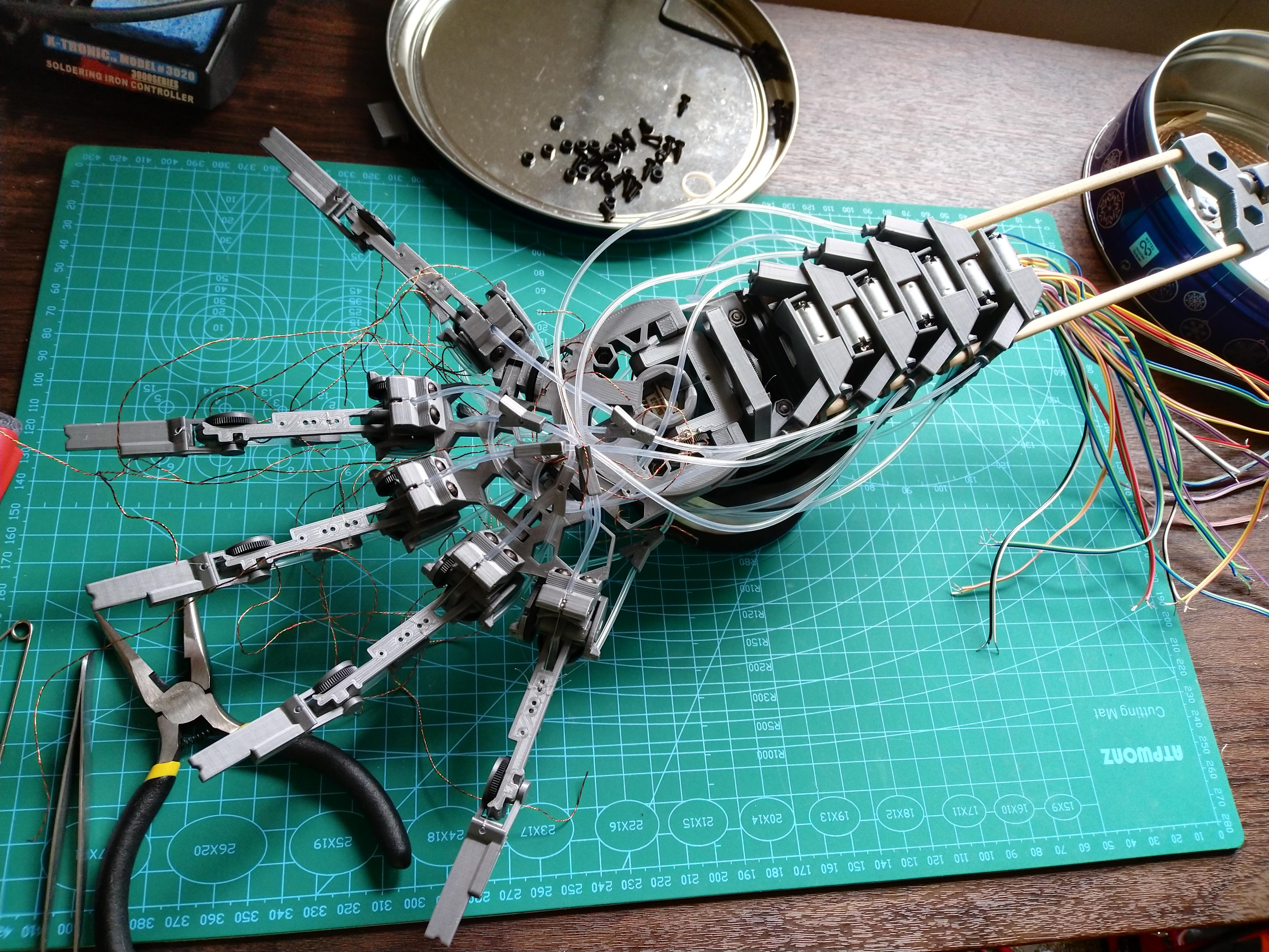
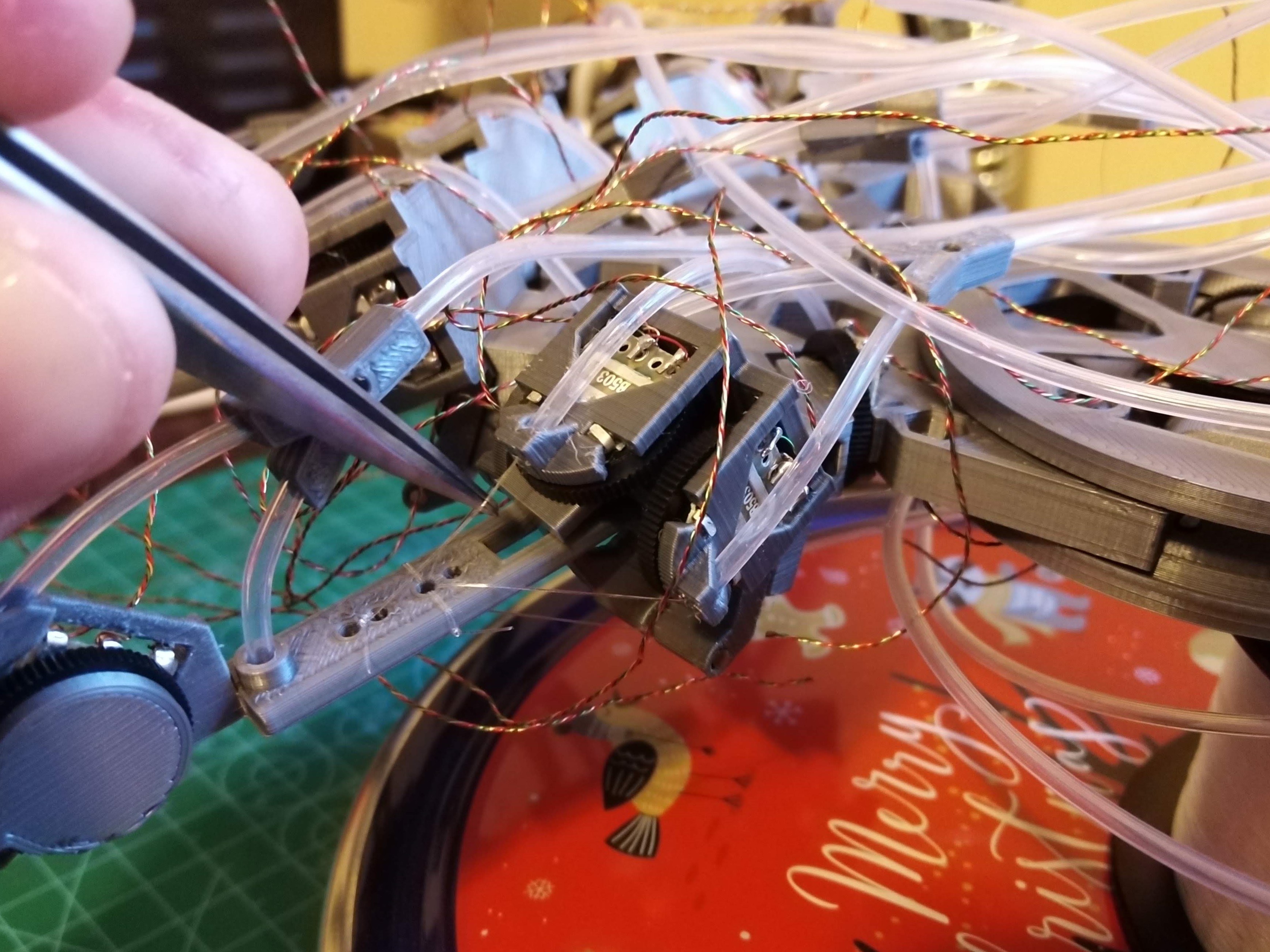
Here’s how it looks like assembled with motors for the first time:
Modelling
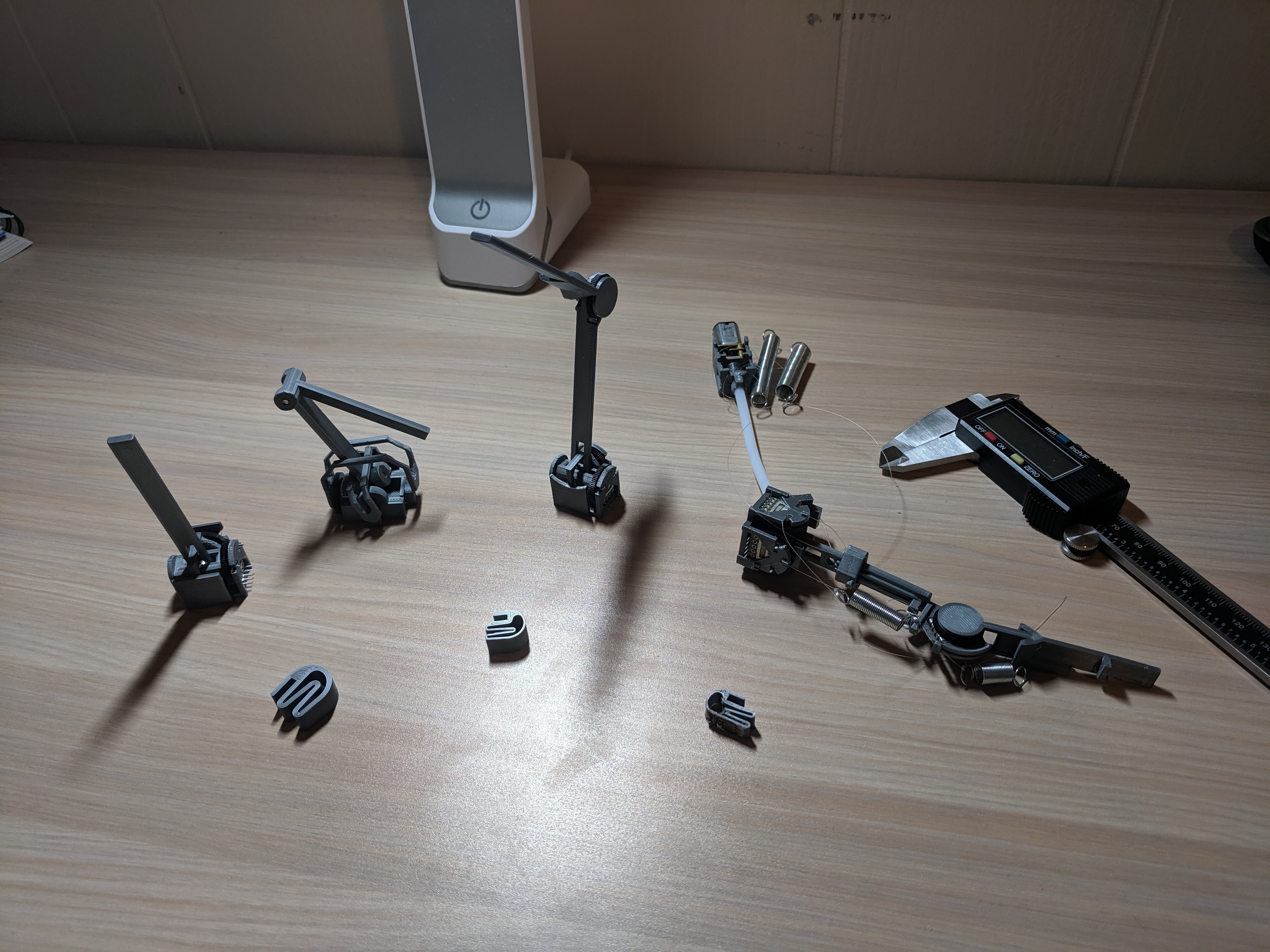
This is a rundown of the initial hand design and how many iterations I’ve gone through for each part. As my first 3D printed project I had to print quite a few iterations to understand what’s possible and what’s not with FDM printing. First lesson was to print parts sequentially, as the printer head leaves a lot of strings when it moves between components. The second lesson was on how bridging works, or rather doesn’t work when you want very precise dimensions. Because we print layers of plastic on top of each-other we always need something on the layer below for the plastic to stick to. We can go up to 60° away from vertical before the plastic starts to droop down too much. And finally I learned that tiny bits of plastic don’t stick enough to the printer bed and the Kraken hits you with a stringy mess. The last issue is really annoying when you’re trying to make small mechanisms… But at least the parts print fast.
With that said, onwards through my design history. Every paragraph below is roughly a whole prototyping day:
- Make a pulley to act like tendons and muscles for the hand:
- First version really bad because I’m new to 3D printing, parts stuck together, and strings everywhere.
- Second version fits better, but needs more tweaking.
- 3rd iteration works pretty nice.
Of-course the “final” pulley was very far from final. Even if it looks like a simple part, it turned out to require a lot of work in the end. The issues with the version above is that I’m routing the nylon wire all around the plastic, introducing a lot of friction points unnecessarily. I’ll later fix this by simply pulling the strings sideways. But another more challenging issue is that I lack any means to tension up the nylon wires. We’ll get back to that later.
- Design a finger:
- Initially I wanted to use xbox joysticks as 2D joints, but they don’t work because they don’t allow much movement.
- I designed a couple of versions of the skeleton with double bearings for every joint.
- Can only find cheap potentiometers for adjusting volume instead of ones with a shaft hole, have to improvise a connector.
- Putting the potentiometer on the same axis with a bearing requires a tiny fitting part that doesn’t stay in, and really brittle construction.
- Flipping potentiometer and having bridges span the axel makes for a huge 2D joint.
- Replaced one of the bearings with a potentiometer, much smaller, but still big. The 2nd axis bridge is still too large, flimsy and gets in the way.
- Put the bridge through the finger shaft. Can make the 2D joint as small as the potentiometer widths and much stronger.
- To be able to print it, I need an interlocking piece to affix the tip shaft to the bearing.
- Stringing the tendons was a bit tough, but managed to rout it around the finger and through the middle. First test of the finger seems to work awesome.
- Need to improve stringing because any bend around plastic puts a lot of friction on the string. I have a plan to ditch most bends, including the servo housing shenanigans.
Every finger iteration got smaller and smaller until I reached the size of the cheap potentiometers I bought. Turns out it’s really hard to search for potentiometers with a hole in them. Especially if you want them to be extra cheap. After I built the hand I found some that are tinier, maybe I’ll redesign it after the electronics.
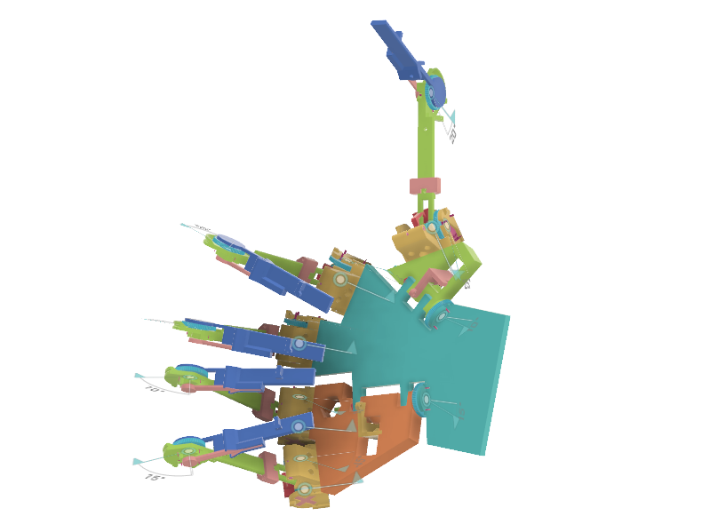
- Modelling the palm:
- Making the palm from 3 pieces so that the thumb and pinkie can pivot to get opposable thumbs.
- Custom bearing for the wrist joint. Needs to take axial loads, so can’t use the tiny bearings.
- Realized that hand/forearm rotation also needs to be measured, which means a rotation point, so we need another bearing. Making the wrist a 3D joint using 2 custom plastic bearings.
- Made the joint and barely fit all the nuts.
- Added the pivots to all the moving parts. Maybe the thumb and pinkie springs are not that good of an idea.
- Printed everything and it fits awesome \O.O/ (on the 3rd try).
- Put a lot more holes in the palm. Not sure if I can make it thinner as I need space for bearings/pots/balls etc.
- Minor fixes:
- Make sure the thinnest layers are 0.5mm as printing thinner leads to dotting.
- Chamfer the top layer of railing so there’s no hidden overhangs. Especially useful to make the bearing rails smooth.
- Chamfer the bottom layer as the first layer is squished making holes too tight.
- Other:
- Modelled finger tip as a flexible single layer plastic piece.
- Modelled arm part as 2 sticks supported by the motor mounts.
- Made a tiny plastic hook, to tie the nylon to the springs.
- Made a tube fork to split the 2 nylon wires from a single tube to a pair of tubes, when they need to go in different places.
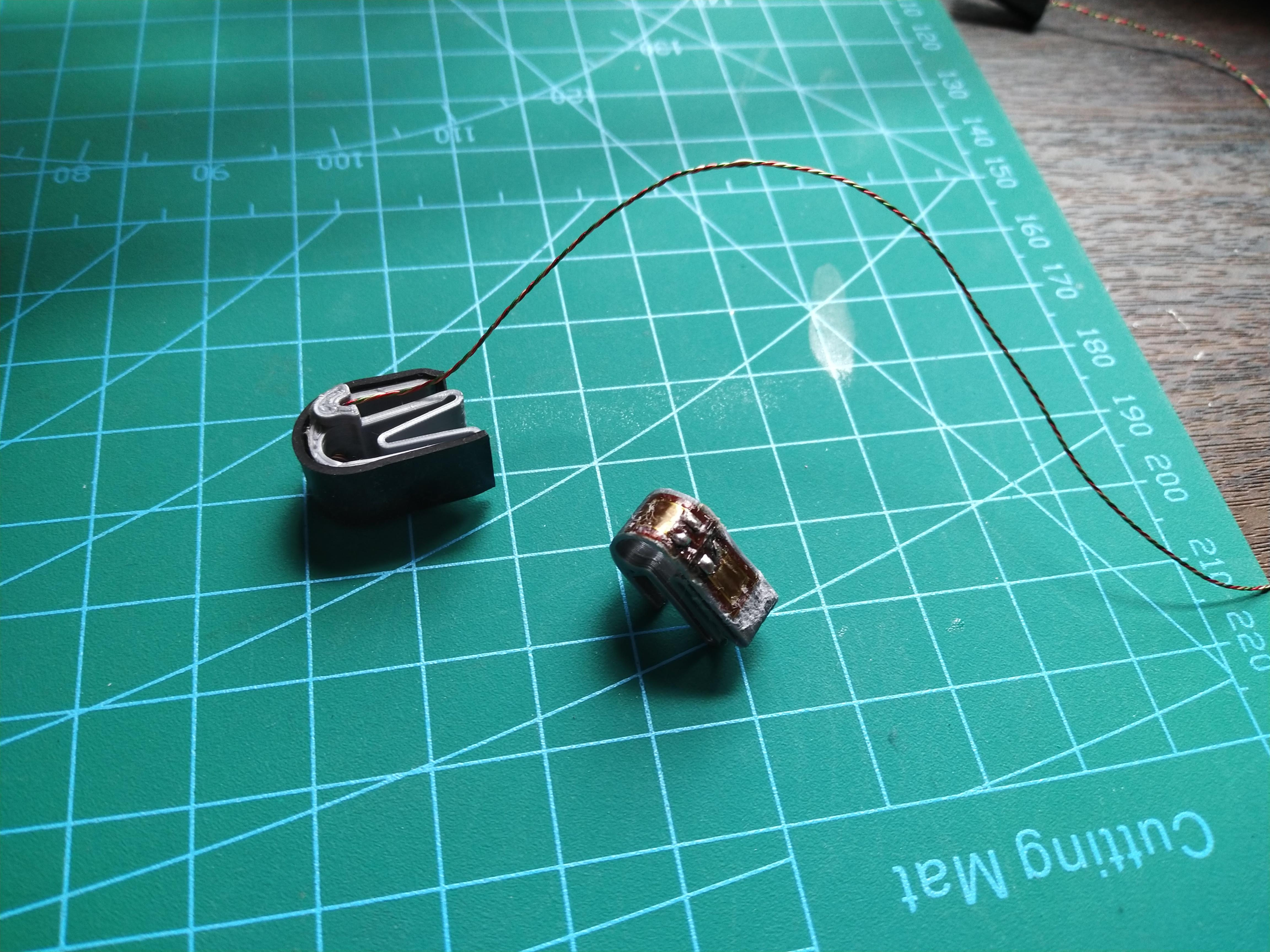
The fingertips are made of a zig-zag plastic piece that’s meant to easily squeeze under pressure. With a stress gauge glued on the part that bends the most, and a second gauge on a flat side to complete one side of an H-bridge. On top of them I glued a thin rubber sheet to protect the gauges and give the fingers some grip.
Iterating
Switched to 1mm tube diameter for flexibility, fits perfectly the 2 wires needed from a motor. Also now routing wires directly to the pivot points to avoid routing through plastic as the friction is too much. Also optimized the pulley housing to removing the plastic tracks.
Holy Glob, gluing and soldering the stress gauges is an absolute pain. Tried getting a hot air gun but it melts the plastic, got to stick with soldering with the hot stick. Also no way to put the wires on first as it melts the gauges. Must mount gauges then solder.
Turns out if the stress gauges are stretched too much, especially near the soldering pads, they break. Surprise! Had to thicken the fingertip wall and invert the gauge, so the solder pads are compressed by the wires instead of stretched. Works like a charm now!
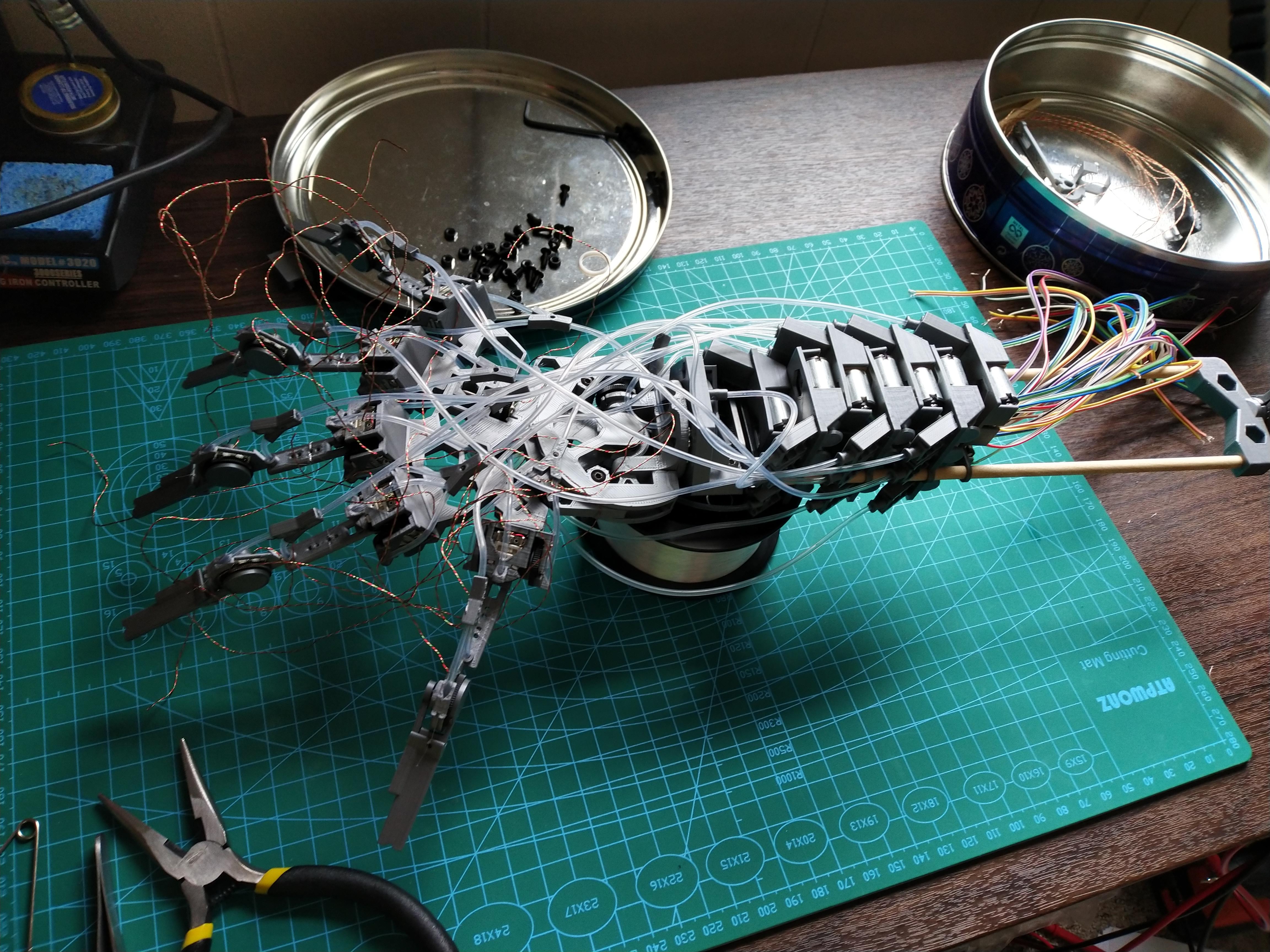
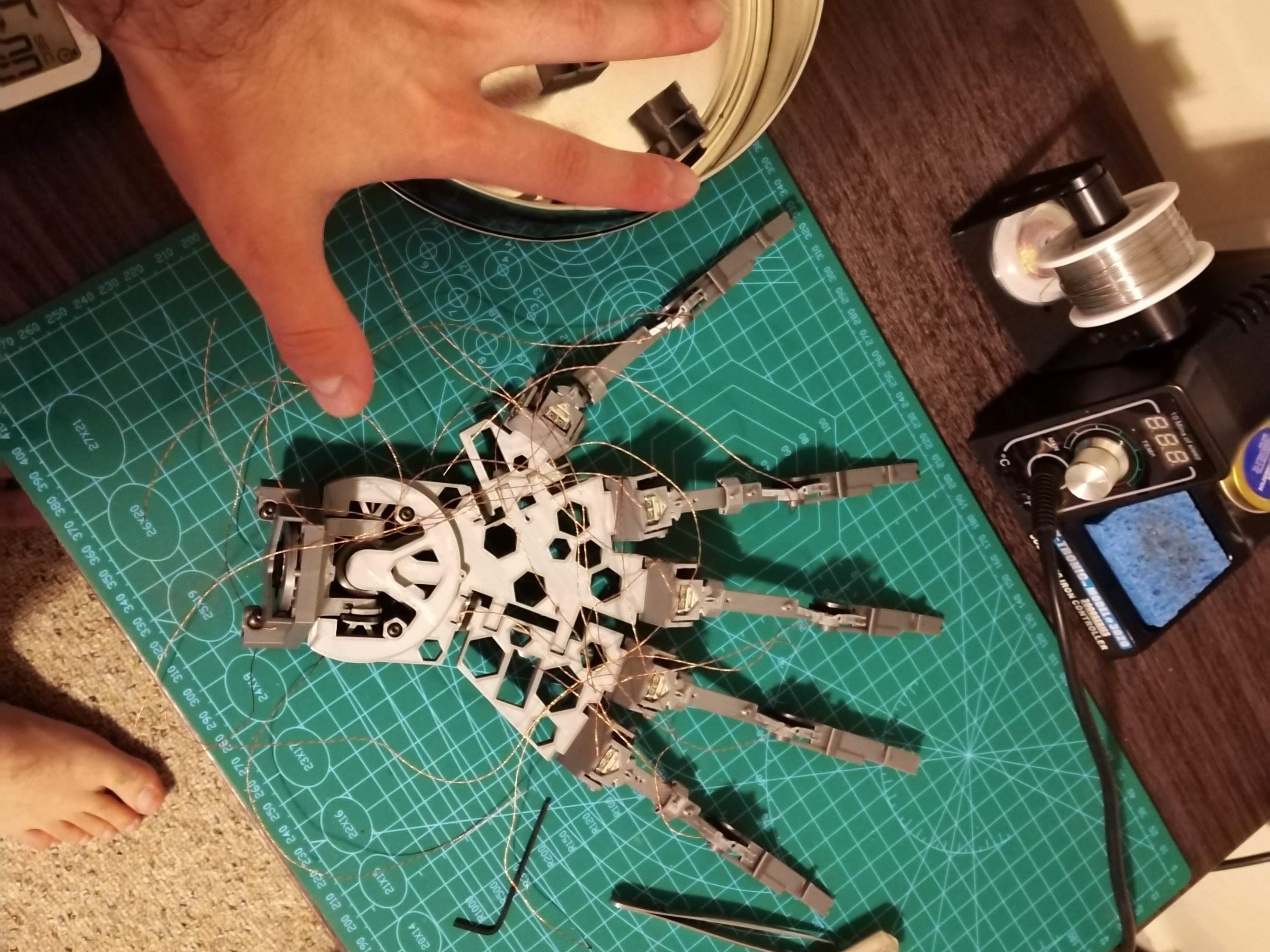
First assembly including wires! Absolute unit of a hand.
And it’s garbage! The 1mm thin PTFE tubes are too thin to support any weight, have to redesign back to thicker tubes. Will also redesign to be a tad smaller. Time to chop some fingers. Having springs all over the place was a bad also idea, I will change to some tensioning screws near the motors and rely on the nylon elasticity. We have to pull the nylon wires pretty tight to overcome the compression in the PTFE tubes.
Got new tubes and redesigned/re-printed holes to fit them. Also made the hand smaller. But holy fucking Christ, tying up the nylon wires and keeping tension on them is a major pain in the arse. Also even with thicker tubes, turns out long ones still don’t work so well, and because I only added a tiny screw for tensioning, there’s no way to account for the deformation and there’s so much lag in movement. Need shorter tubes and better tensioning device.
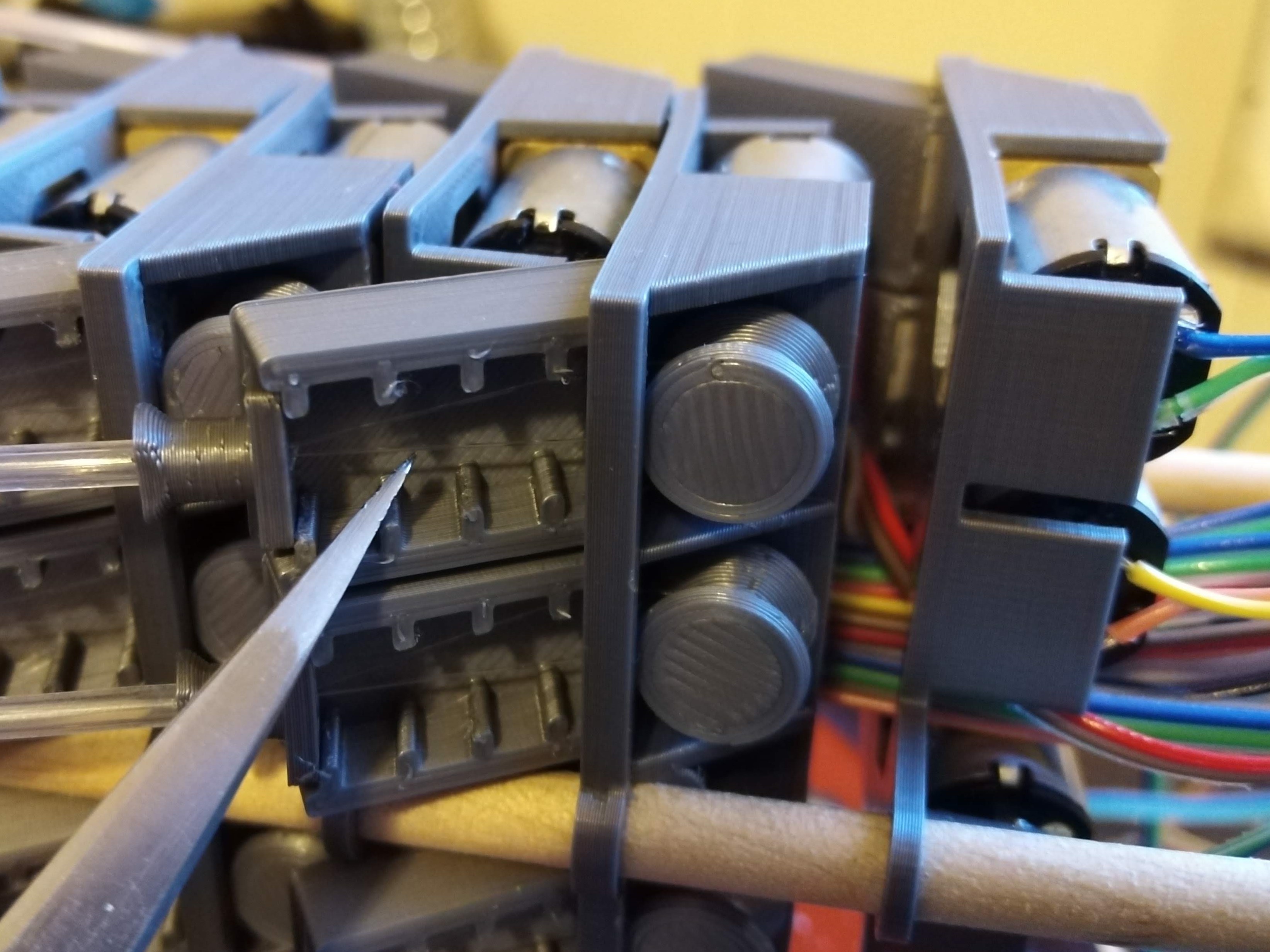
Redesigned housing to fit 4 motors on one side. Placing them on alternating sides so we have space for wires. But it’s too wide and too tall. I had to redesign it again with 3 motors per layer, but 2 on top and 1 on the bottom so it’s only tall on the top side.
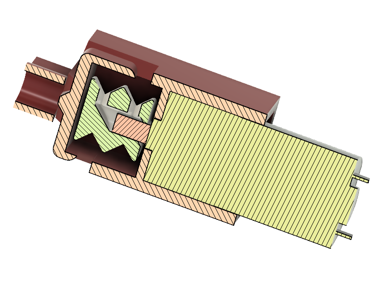
Much work on the spindle and tensioner design. Opted for a single rail spindle, and just looping the wire around it and relying on tension and friction. That should simplify wiring a bit. For the tensioner I tried 4 designs. The original one is tightened with a 8mm screw, but that’s too short to tighten significantly and because the plastic is hard, it’s also difficult to wire it, as it needs tension while tying knots. Next 2 designs involved a wheel with one way teeth that will pull the string tight. But the wheel needed to be small enough to fit on the spindle which doesn’t allow enough length for the teeth to bend so it can only turn one way. Either the teeth are too small and they break, or they don’t bend at all. Alternative locking mechanism involved teeth perpendicular to surface. They lock in place by the tension of the wires. But this causes the wire to wrap around itself which leads to breaking it. Tried to place a rod to guide the wire around it, but it doesn’t work. 4th and hopefully final design is a staircase with a knob. I place the wire tube on the knob and pull it as high on the stairs as I can. It’s then held in place by wire tension.
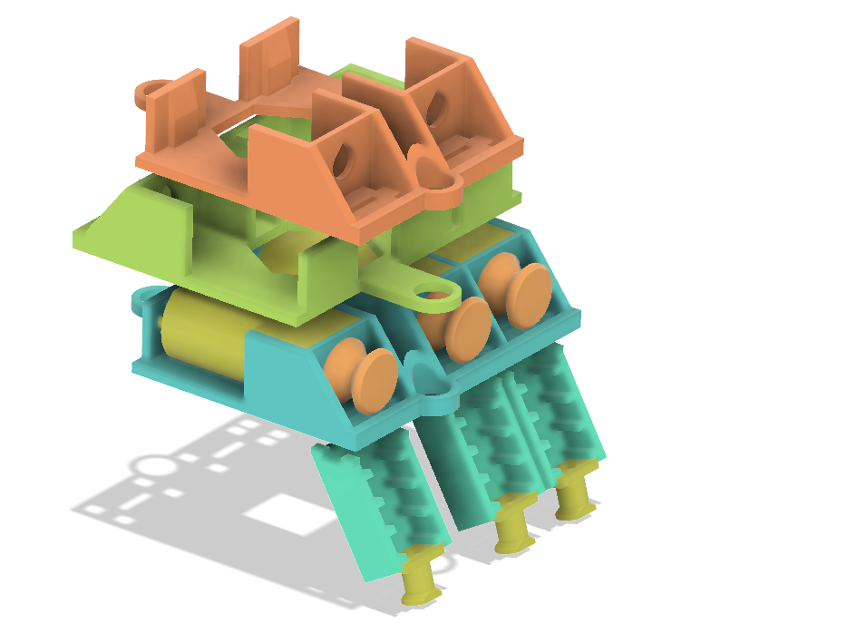
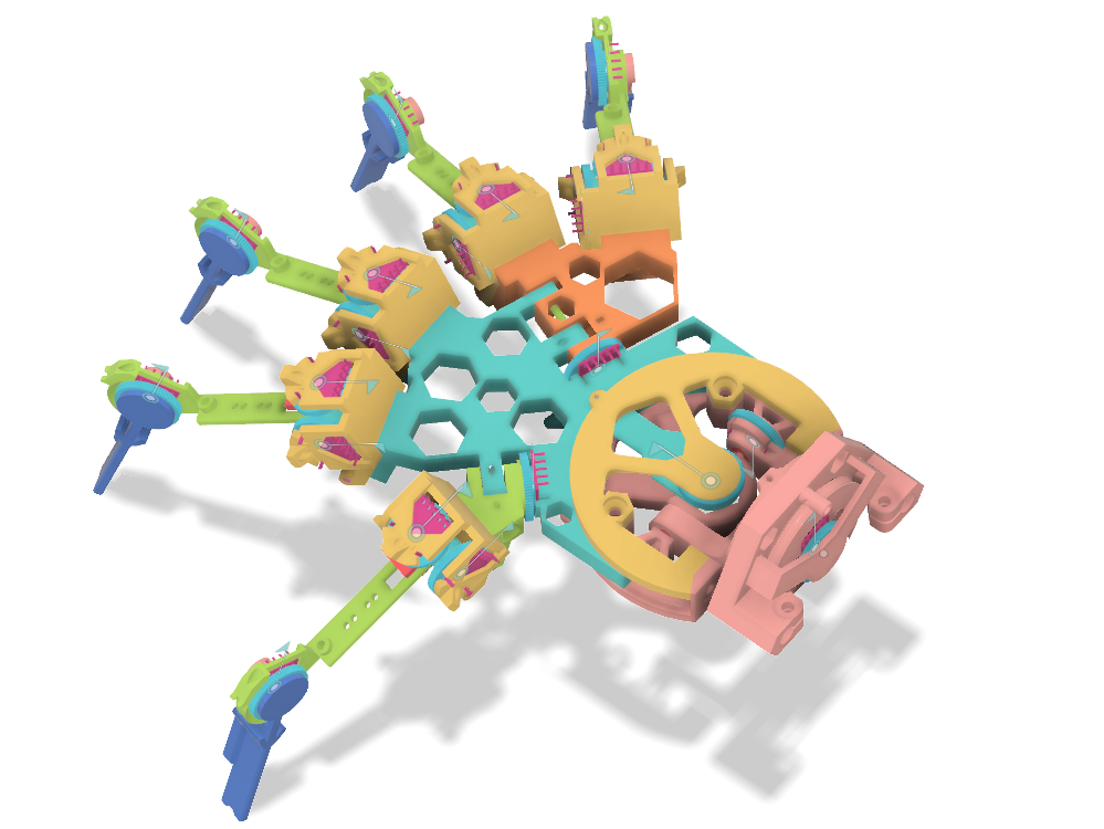
I did not include the nylon wires and tubes in the 3D model. But as you can see in the close-ups below, the fingers are actuated by a pulley system. A nylon wire runs through a spindle around the motor shaft, it’s routed through the PTFE tubes to the fingers and then tied on the finger sections from both sides. Spinning the motor one way tightens one side and loosens the other, driving the finger in that direction. Spinning the motor the other way does the opposite and drives the finger back. This is the same principle that bicycles use to drive the breaks and gears.
It’s Working
First assembly with motors, and it works!
Up next, I need to wire everything to an ESP32 and an Arduino to measure all the joints and control the motors. Yes, I need both chips to have enough GPIO pins to do everything. Even then I need a few extra IC like the PCA9685 led driver to control 16 motor speeds using just 2 I2C wires, and L293D H-bridges to control the direction of each motor, with possibly a few shift registers if I still run out of GPIO pins. By the way, the ESP32 chip looks amazing with 18 ADC inputs and WiFi and Bluetooth.